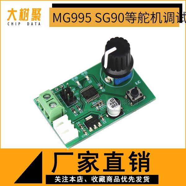
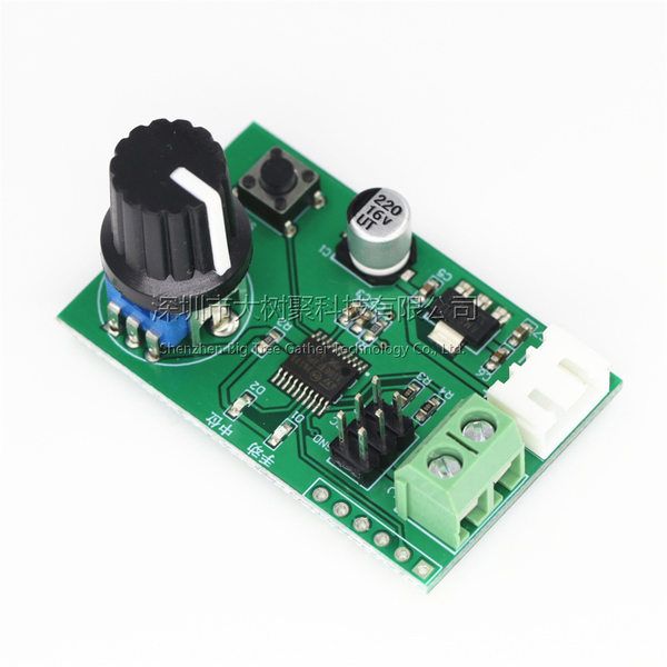
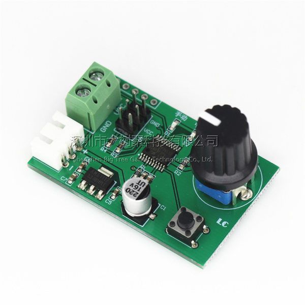
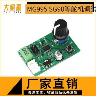
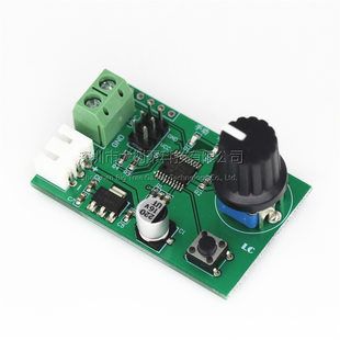
Двухканальная ручка рулевого механизма, плата управления последовательным портом MG995 SG90 и другие платы отладки рулевого механизма, инструмент для возвратного центрирования
Ссылка на оригинал- 100 — 1999 шт 5000$ за шт.
- 2000 — 50119 шт 4000$ за шт.
- 50120+ шт 3000$ за шт.
Проверка + фотоотчёт за 1.5$
Мы проверяем товар и делаем фотоотчёт, чтобы вы могли убедиться, что получите нужный товар без брака и повреждений.
Доставка из Китая в Украину, Узбекистан, страны Европы.
Оплачивается по прибытию на склад в Китае
Возврат товара возможен только пока товар находится у нас на складе в Китае. После отправки из Китая товар возврату не подлежит.
Фото и описание товара
双路舵机 旋钮 串口控制板舵机调试板回中仪
(详情提供中英文描述)

中文描述:
一、 概述
旋钮舵机控制模块是一款即插即用,简单易上手的舵机控制器,具备旋钮调节、回中功能、串口指令控制三种舵机控制方式。
二、 功能特点
1、板载成熟稳定的8位MCU用于产生高分辨率的PWM信号,控制精准;
2、支持手动模式和回中模式,通过按键切换,带模式指示灯;
3、手动模式下支持旋钮调节或者串口指令控制;
4、串口指令控制时可使用配套的上位机或者连接外部MCU;
5、控制通道数:2路(M0和M1号舵机),使用旋钮调节和回中功能时2路舵机同时控制,使用串口指令时2路舵机可分别控制;
6、舵机控制精度:0.09度(即PWM小变化值1us)
7、支持控制周期为20ms,脉宽在0.5-2.5ms区间的舵机(如Futaba,辉胜等)
8、可直接使用2S锂电池充电头调试并回中舵机
9、电源电压范围:5-9V(具体以实际所用舵机供电电压为准)
三、硬件介绍和说明
1、板子尺寸:29.8*47.2mm
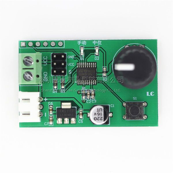
2、板子接口说明:
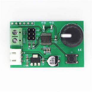
VCC、GND:电源接口;
XH2.54mm座子:备用电源接口,可接2S锂电池;
2X3P排针:2路舵机接口;
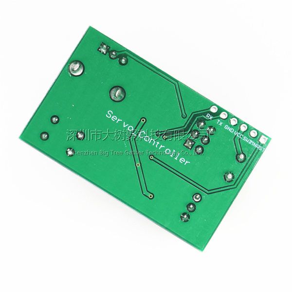
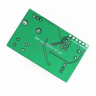
TX、RX:UART串口引脚;
SWIM、NRST:预留单片机程序下载口。
3、使用说明:
1.1. 关于接线:
VCC、GND接电源,将舵机插在2X3P排针处,其中VCC为正极,GND为负极,S为信号端。
1.2. 手动模式:
通过板载按键选择手动模式,此时手动灯点亮,中位灯熄灭。
手动模式包括旋钮控制和串口控制,默认为旋钮控制,2种控制方式系统会自动切换,即检测到电位器有转动时选择旋钮控制,串口接收到有效的控制指令时选择串口控制。
2.1旋钮控制:
直接转动电位器即可控制舵机在0-180°范围内转动
2.2串口控制:
板载MCU可以接收解析来自上位机、外部MCU等设备发过来的舵机位置指令(波特率9600,兼容3.3V/5V电平),从而分别控制2路舵机,其中舵机位置指令格式为:#P!,各自含义如下:
a, #号为起始符号,不可缺少;
b,表示所控制的是第几路舵机,共2路(范围:00-01分别对应舵机M0和M1);
c,P为指令格式中固定符号,不可缺少;
d, 表示PWM信号的宽度(范围:0500-2500分别对应0-180°);
e, !为指令的结束符号,表示一条指令的结束,不可缺少。
比如:发送#00P1500!即可使舵机M0转动到90°位置
发送#01P1000!即可使舵机M1转动到45°位置
以连接开发的上位机LCSC为例,准备个USB转一TTL串口模块(如CH340、FT232等),串口模块的TX、RX、GND分别接控制板的RX、TX、GND,选择正确的端口号,连接成功后拖动0号和1号进度条即可分别控制M0和M1号舵机,如下图:

1. 回中模式:
通过板载按键选择回中模式,此时手动灯熄灭,中位灯点亮,舵机M0和M1会同时归于中位。
温馨提示:
因为舵机属于比较耗电的器件(如MG995/MG996舵机),所以给舵机供电的电源电流需充足,当舵机转动时如果板载的LED出现闪烁现象、舵机不受控或者误差明显偏大等异常现象时,说明电源电流不够需更换电源。
英文描述:
1.Description:
The servo control module is a plug-and-play, easy-to-use servo controller.Supply three servo control modes : Knob adjustment, back to center function.It can be used to test servo motor.
2.Features:
1>.Support manual control;
2>.Support UART control;
3>.Support back to function;
4>.Support 2pcs servo motors at the same time;
5>.High precision;
6>.MCU STM8S103 Output high precision PWM signal;
7>.Button change work mode;
8>.Support 2S chargeable lithium battery.
3.Parameters:
1>.Input voltage: DC 5V-9V(change according to actual);
2>.Control channel:2CH;
3>.Control precision:0.09°;
4>.Color:Green;
5>.Support cycle:20ms;
6>.Support servo motor:Pulse Width 0.5s~2.5s ;
7>.Operating Temperature:-20℃~70℃;
8>.Operating Humidity:5%-90%RH;
9>.Size:48*30*30mm;
4.Wiring method:
Users can input voltage from green terminal or white XH2.54mm female socket.
It just need connect to power supply and motor if users no need control servo motor by PC or MCU.
It need connect to PC or MCU if control servo by PC or MCU.We can provide a soft for PC.But users need write code by yourself and we can not provide test code.Because the controllers used by each person are different.Request your understanding!
Step 1:Connect input power supply at input terminal;
Step 2:Connect servo motor at 2*3Pin black male pins;
VCC:It connects to positive pole at servo motor;
GND:It connects to negative pole at servo motor;
S:It connects to input signal at servo motor.
5.Manual Control:
Select to Manual Control by button ‘S’ when LED indicator D1 is turn ON and D2 will OFF;
Manual Control include Knob Control and UART Control.The default is Knob Control.Automatic switching between two control modes.In other words, select the knob mode when checking that the potentiometer is rotating.Select UART mode when the UART receives a valid signal.
5.1>Knob Control:
Directly rotate the potentiometer, the servo motor will change angle with rotation.
Rotation angle range 0~180°.
Two servo motor will make the same action if connect to two servo motor.
5.2>.UART Control:
It can get UART command signal from PC soft or MCU.Baud rate is 9600 and compatible 3.3V/5V TTL level signal.It can control 2pcs servo motors separately.
Command format and description:#P!
5.2.1>.#:Starting symbol, indispensable;
5.2.2>.:Servo motor number.Range is 00 or 01;
5.2.3>.P:Fixed symbol, indispensable;
5.2.4>.:PWM width.Rang is 0500~2500 corresponding to 0~180°.
5.2.5>.!:Fixed symbol, indispensable;
For example:
Send #00P1500! means servo motor M0 turn to position at 90°.
Send #01P1000! means servo motor M1 turn to position at 45°.
Users can also not send commands but just operate on control soft.
6.Back to center function:
Select to Back to Center Control by button ‘S’ when LED indicator D2 is turn ON and D1 will OFF.
Servo motor M0 and M1 will turn to center when select this mode.
7.Note:
1>.Please provide enough power, otherwise the module or servo motor may not work properly.
2>.Situation by power shortage:LED indicator blinks;Servo motor is not controlled.It need add input current in these situation.
3>.The control software LCSC supports Chinese and English. After installation, the Chinese language is displayed by default. Users can choose to display English as shown in description picture.
8.Application:
1>.Smart robot;
2>.Aircraft;
3>.Toy production;
4>.Education;
5>.Technology display;
9.Package
1>.1pcs 2-Channel Servo Motor Controller;
图片展示:


 South Africa
 Nigeria

